
301 Moved Permanently
Support for module-level power electronics (MLPE) has grown recently in the U.S. solar market. There are not only code requirements that promote MLPE solutions, but also design, installation and support considerations, including ongoing operations and maintenance (O&M). In addition, there are performance and availability factors that support the use of MLPE systems with practical safeguarding.
In a design comparison among string inverters, micro-inverters and DC/DC converters, a main difference would be the distance calculations on the DC and AC sides of the PV system. Because of the difference in voltage on the DC side, there is a difference in sizing due to voltage drop and power loss with higher currents.
Typically, there is less of a voltage tolerance boundary - for instance, ANSI C84.1 - on the AC side than on the DC side. However, for DC/DC converters, based on lower operating voltages and higher currents, conductor sizes in a ground-mounted system may necessitate larger wire sizes because of the distance not only on the DC side, but also on the AC side.
The best practice for minimizing wire sizes for traditional string inverters would be to place the inverter near the AC point of interconnection for the inverter output circuit. The AC point of connection typically provides better diagnostics than the DC side.
Another MLPE design consideration is the impact of degradation. For example, a recent report from the National Renewable Energy Laboratory discusses the “Outdoor PV Module Degradation of Current-Voltage Parameters.” If using MLPE, the impact of degradation could influence the performance mismatch, as the modules degrade with the changes in the IV curves of each individual module.

From a design perspective, voltage drop and power loss are the main considerations when assessing the AC inverter output circuit and DC/DC converters. Specifically, because there is typically less of a voltage tolerance boundary on the AC side, the wiring of the modules may have to be split to a junction box to minimize voltage drop. On the DC side, the ampacity calculations are simplified, considering the current at short circuit, maximum current and continuous current. Again, the conductors would be sized based on the greater difference between ampacity and voltage drop.
Installation issues
MLPE may be attached to either the rail or the module. In special situations, the MLPE is listed as an AC module.
From an installer perspective, this may present an issue with accessibility and safety if there is an MLPE failure. In accordance with the National Electrical Code (NEC)/NFPA 70, on the rooftop, the MLPE become “accessible” but not “readily accessible.” Conversely, string inverter systems are typically “readily accessible.”
Also, there are different connectors between micro-inverter and DC/DC converters. The connectors for DC/DC converters are the ones typically used in a traditional string inverter implementation. As a result, there are different installation techniques for both types of cable connectors. From a design perspective, with the use of DC/DC converters, the number of strings is typically reduced. As a result, from the installer’s point of view, the number of installed conductors is minimized.
In situations where the fixed voltage of the photovoltaic output circuit is more advantageous in a DC/AC inversion, there may be comparisons in shading tolerance and differences in reliability. On the other hand, with larger power inverters, there would be reliability, availability and maintenance of the fans. Conversely, a micro-inverter solution would not require the maintenance of fans, but there would be other potential reliability issues in the MLPE in comparison to DC/DC optimizers and inverter components.
For example, in a traditional string inverter solution, every module in a string is affected by the failure of one module. This is particularly pronounced in systems with higher DC voltages and longer string lengths. Conversely, in an MLPE solution, the effect of one defective module would be limited to that one module. In turn, the difference in overall system reliability and ongoing maintenance could be significant.
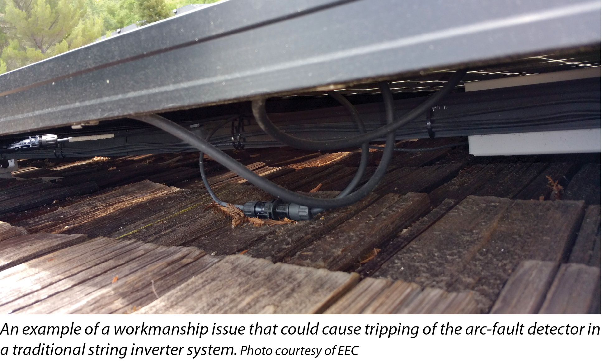
There are also issues related to arc faults. NEC 690.11 notes that “photovoltaic systems with DC source circuits, DC output circuits or both, operating at a PV system maximum system voltage of 80 V or greater, shall be protected by a listed arc-fault circuit interrupter.”
Because MLPE system solutions for modules are less than 80 V, from a support perspective, “the system shall require that the disabled or disconnected equipment be manually restarted” in accordance with NEC 690.11(2). The need for manual restarting affects the availability of the system.
Ultimately, both MLPE and traditional inverter systems must be serviced in some way when safety issues arise. In either scenario, qualified installers and O&M technicians should be deployed.
From an inspection perspective, residential installations represent the bulk of the workload in most jurisdictions, compared with commercial and industrial PV systems. In the past, MLPE-based systems were difficult to get through the permitting phase, and post-installation inspections were more complicated because of the many disconnection points in the system. But today, MLPE systems are becoming common in the residential sector, and inspectors are more familiar with these increasingly popular installations.
Power Electronics
PV Systems At The Module Level
By Martin E. Herzfeld
The continued growth of MLPE technology in PV arrays is influencing system design and installation practices.
si body si body i si body bi si body b
si depbio
- si bullets
si sh
si subhead
pullquote
si first graph
si sh no rule
si last graph