

301 Moved Permanently
If there is one thing that every installer, engineer and designer can agree on, it is that there has been no universal consensus on the definition of acceptable photovoltaic infrastructure labeling. While labeling is required on the entire PV system, it is important to include your combiner boxes, wiring and wiring connections. The industry is young, and the codes and regulations are so diverse that most installers are left on their own to figure out how to ensure they pass inspection while still meeting the labeling requirements of the National Electrical Code (NEC) and the International Fire Code (IFC). Both standards go hand in hand and address key issues of PV labeling.
The new NEC 2014 code goes a long way to bridging the label gap between the two standards. Because of concerns about the safety of first responders and emergency personnel, the IFC 2012 took the step of defining details about specific label formats that were designed to be highly visible in emergency situations. Section 690 of the 2011 edition of the NEC code outlined the basic parameters for labeling, while the IFC went a step further in defining the size of text, color and physical properties of the label. The IFC label requirements are now supported and reinforced in the new code requirements of Article 690.
However, there is still a lot of confusion and misunderstood information when it comes to photovoltaic labeling, including connectors and junction boxes and the related cables within a typical combiner box or within the electrical metallic tubing (EMT) conduit. It is not uncommon for an installer to believe that the use of etched plates are a directive of the NEC code or that markers are mandated to last more than 20 years on a solar installation. Yet, what are the true requisites of PV system labeling? How should an installer address the complex and often diverse issues regarding labeling and how that relates to passing inspections by the authority having jurisdiction?
First, the NEC and IFC do not identify a particular method of marking the infrastructure.
In NEC 2008, there is a phrase that reads as follows: “The labels are required to be a durable, unalterable material permanently attached to the device. The most common type of labeling is engraved or etched plastic, which can be riveted or adhered to the device.”
This statement simply indicates that the most common type in use in 2008 was an engraved plate. For years, many inspectors and installers have interpreted this to mean that an etched plate is mandatory in order to pass inspection and have the marker last over 20 years.
In the new NEC 2014 code, the code panel made a specific point of using the word “LABEL” to better define the method of marking. Some examples from the NEC 2014 code include the following:
- NEC 110.21(B): “Where required in this code, any field applied LABELS, warning(s) and marking shall comply with ANSI Z535.4.”
- NEC 110.21(B)(5): “ANSI Z535.4 - 2011 Product Safety Signs and LABELS provides guidelines for the design and durability of safety signs and labels for the application to electrical equipment.”
All other warning and caution labels, unless otherwise specified, must meet the requirements of American National Standard Institute (ANSI) Z535.4 - 2011 per Article 110.21(B) in the NEC 2014. The ANSI standard requires that danger, warning and caution signs use the standard header colors, header text and safety alert symbol on each label. The ANSI standard requires a heading that is at least 50% taller than the body text. While not required in the NEC 2014, the message text should be at least 0.12” tall. If we compare this to Occupational Safety and Health Administration 1910.145 and ANSI Z535, it is specified that signs must be visible at a safe viewing distance from the hazard. They also recommend the use of safety alert symbols where applicable.
In the NEC 2011 code, the label shown in Figure 1, which would typically be applied to a combiner box or enclosure, is currently acceptable.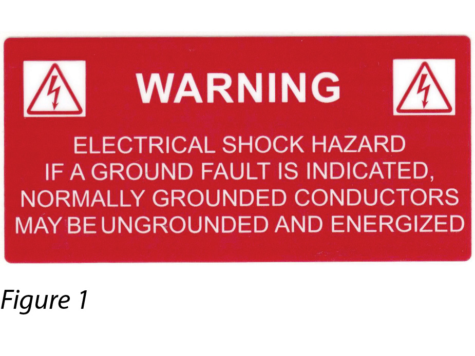
In the NEC 2014 code, the format of this same label would look as shown in Figure 2.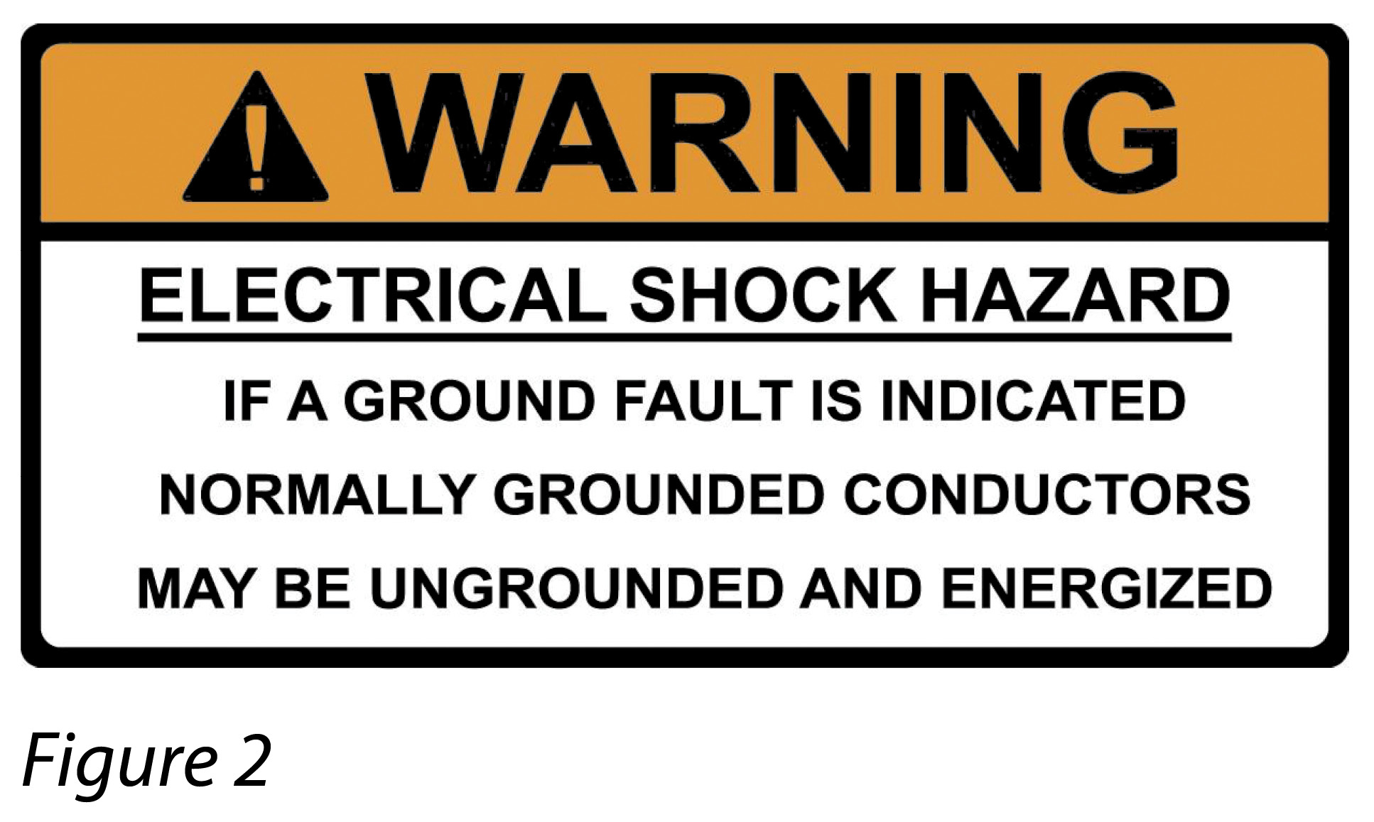
The text is the same. The only difference is that the second label is designed based on the requirements of ANSI Z535.4.
The orange header color serves to satisfy the new code requirements when approving installations. On the one hand, this appears to make the work of labeling more complex. However, it also allows the market to now provide a variety of labeling packages that are pre-made for use by installers, cutting time and costs out of the process.
Continuing with the junction box, Article 690.35(F) states that a PV power source shall be labeled at each junction box, combiner box or disconnect where energized; ungrounded circuits may be exposed during service.
In addition, Article 110.27(C) requires that a label also be placed on the combiner box based on the fact that any guarded locations that contain exposed live parts shall be marked with conspicuous warning signs forbidding unqualified persons to enter, as shown in Figure 3.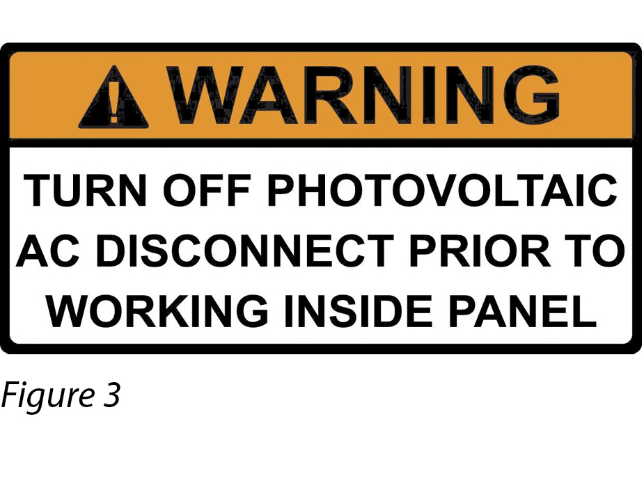
Finally, Article 690.17(E) requires a warning label on the combiner box or enclosure if the terminals of the disconnect may be energized in the open position. Remember that your combiner box may be energized from both sides by the other combiner boxes around it. The label includes an additional warning regarding the DC voltage and solar array, as shown in Figure 4.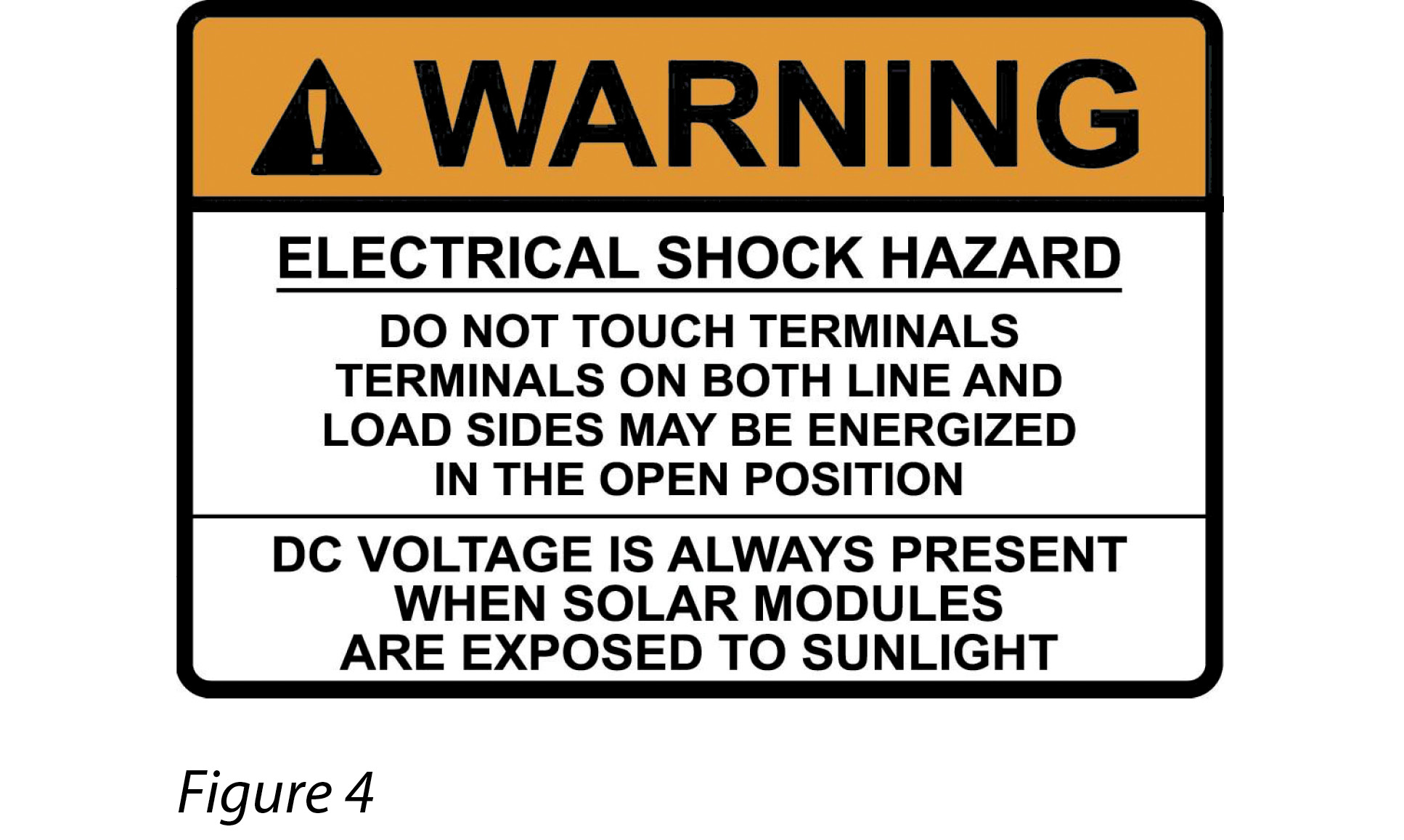
There is a new label in the NEC 2014 code that indirectly affects the labeling of the combiner boxes. There are now some labels that are defined specifically within the standard that do not conform to the ANSI standard and, instead, follow IFC guidelines. These labels have specific warnings that require high visibility and, in some cases, reflectivity.
One new and very important requirement is found in NEC690.56(B), which specifies the need for a “rapid shutdown” switch. This switch, when activated, is required to reduce voltage to 30 VDC within 10 seconds inside the building and within 10 feet from the array.
The rapid shutdown switch is required to have a reflective label that reads “PHOTOVOLTAIC SYSTEM EQUIPPED WITH RAPID SHUTDOWN” printed with 3/8” tall white letters on a red background. This label would be applied to a separate breaker or switch that comes after the utility meter and connects directly to the combiner boxes, which would be used if the system has a battery backup system. If the installation does not include a battery backup system, the label will be applied to the main AC disconnect. Future equipment will most likely be designed to enable the shutdown of the system as required in the new code. This label would be applied to that equipment.
As mentioned earlier, many inspectors and installers believe the use of an etched plate is required in order to pass inspection and that the marker must last for 20 years. In the new NEC 2014 code, the language was modified to include the word “LABEL” within the code as follows:
- NEC 110.21: “The LABEL shall be suitable for the environment where it is installed.”
This means that the label should be designed to withstand the outdoor elements but does not specify a time period.
So, what does that mean for customers, designers or municipalities that seem fixed on having a 20-year rating for labels used on field-marked equipment? First, there is no drawback to using an engraved plate, but an installer needs to be aware that most phenolics are not ultraviolet (UV) rated for outdoor use. Engraved plates can be costly and have limitations when it comes to meeting the requirements of the most recent standards - which now include reflectivity.
The new standards are written to allow an installer to pick from a variety of identification methods. For instance, the IFC 2012 says that the materials used for marking shall be reflective, weather resistant and suitable for the environment.
As mentioned, certain labels do not have to conform to the ANSI standards and some labels need to have reflective characteristics. The NEC and IFC actually go one step further in distinguishing critical labels needed to prevent a life-threatening hazard. It has become imperative that labels provide emergency responders with appropriate warning and guidance with respect to isolating the solar electric system. This includes identifying energized electrical lines (wiring) that connect the solar modules to the inverter, as these should not be cut when venting smoke from a burning building. Cutting into a live conduit could result in a 520 V jolt and cause more arcing and sparks, which may contribute even more to the fire, so safety is a primary concern.
Because fire is a concern, connectors require a label that meets the requirements of Article 690.33(E)(2), which states that a connector interruption of circuit be a type that requires the use of a tool to open and marked as “Do Not Disconnect Under Load.” Attempting to disconnect under load can create sparking and arcing, which can also be a potential fire hazard.
As for wiring, the IFC and NEC specify that EMT conduits and raceways must be marked no less than every 10 feet, at every turn, above and below penetrations and on all exposed raceways, cable trays and other wiring methods. The EMT conduit runs from the array to the combiner boxes and then out to the inverter and breaker systems. As a result, these labels also must be visible on the covers or enclosures of pull boxes and junction boxes, as well as conduit bodies in which any of the available conduit openings are unused.
The new NEC 2014 code finally bridges the gap between the NEC 2011 and IFC 2012, in which the NEC 2011 indicated that the required text should read as “PHOTOVOLTAIC POWER SOURCE,” while the IFC stated that the text should read as “WARNING: PHOTOVOLTAIC POWER SOURCE” and be reflective with 3/8” white characters on a red background. The NEC 2014 panel modified the code to support the IFC requirements so that both codes now agree on wording and format.
So, per the new NEC 2014, the label is to be printed with the following text: WARNING: PHOTOVOLTAIC POWER SOURCE. Further, the NEC and IFC require that these labels have reflective properties so that they are clearly visible in the beam of a flashlight. The IFC is specifying that the markings must be detectable from a distance, which denotes that the minimum text height is 3/8” using white lettering on a red background.
Also, printed labels must now spell out the word “PHOTOVOLTAIC.” The term “PV” is no longer acceptable on a printed label.
Labeling the wiring in a combiner box falls under Article 690.31(B)(1) through (4) for installation. Conductors shall be identified and grouped as required using color codes, tags, marking tape or other means. Where AC and DC are running together, they must be grouped using cable ties and identified clearly.
The NEC 2014 and IFC 2012 offer new insights into the dynamics of labeling the PV installation. The updated standards open the door for the acceptable use of high-quality labeling products that are designed to meet critical UV exposures. These suitable labels also offer a permanent marking on low-energy surfaces, such as powder coat paints found on many of the new breaker boxes and inverters.
These updates come at an opportune time when the market is now capable of supplying label inks and adhesives that are UV stable and have the ability to adhere to various surfaces without losing adhesion due to temperature or environmental changes.
The one caveat that installers must consider are local regulations. Some communities mandate the use of an engraved plate, and in those instances, an installer must comply. Yet, in most districts, there is no specific definition of what type of marker is required. This gives an installer more variability in selecting a labeling solution.
One final bit of advice: Always check local codes before defining labeling formats. S
Product: Pv Connectors & Junction Boxes
New Labels Bring Clarity To PV Infrastructure
By Todd Fries
There is a lot of confusion about labeling combiner boxes, wiring and connectors, but standards help installers sort things out.
si body si body i si body bi si body b
si depbio
- si bullets
si sh
si subhead
pullquote
si first graph
si sh no rule
si last graph