

301 Moved Permanently
In the design of ground-mounted photovoltaic power systems, combiner box locations are often determined by the geometry of the site and the grouping of the modules and racking in the field. Nevertheless, with ground PV arrays employing central inverters, project designers should take more than site geometry into account if they want to optimize system performance.
Given the location of the combiner boxes in a field, their rated current and the sizes of the conductors connecting them to the central inverter, a designer can calculate an optimal location for the inverter that minimizes the total power loss in the conductors. The rated current of combiner boxes is dependent on the number of strings that are terminated in them, and conductor sizes are chosen based on considerations such as the current carrying capacity of the conductor, acceptable voltage drop and availability of the material.
Presented here is a method for finding a location for the inverter that minimizes total conductor Ohmic losses once the appropriate parameters have been selected.
It is assumed that there are no predetermined locations for the inverter dictated by other circumstances and that the inverter is connected to a step-up transformer located in its vicinity, making the power losses to the point of interconnection negligible.
For determining optimal inverter placement, I distinguish two cases that are as follows:
- Homeruns are radially connected to the inverter along single straight lines; and
- Homeruns are connected to the inverter along perpendicular line segments - typically in the direction of the racking and in the direction perpendicular to the racking.
Radially connected homeruns
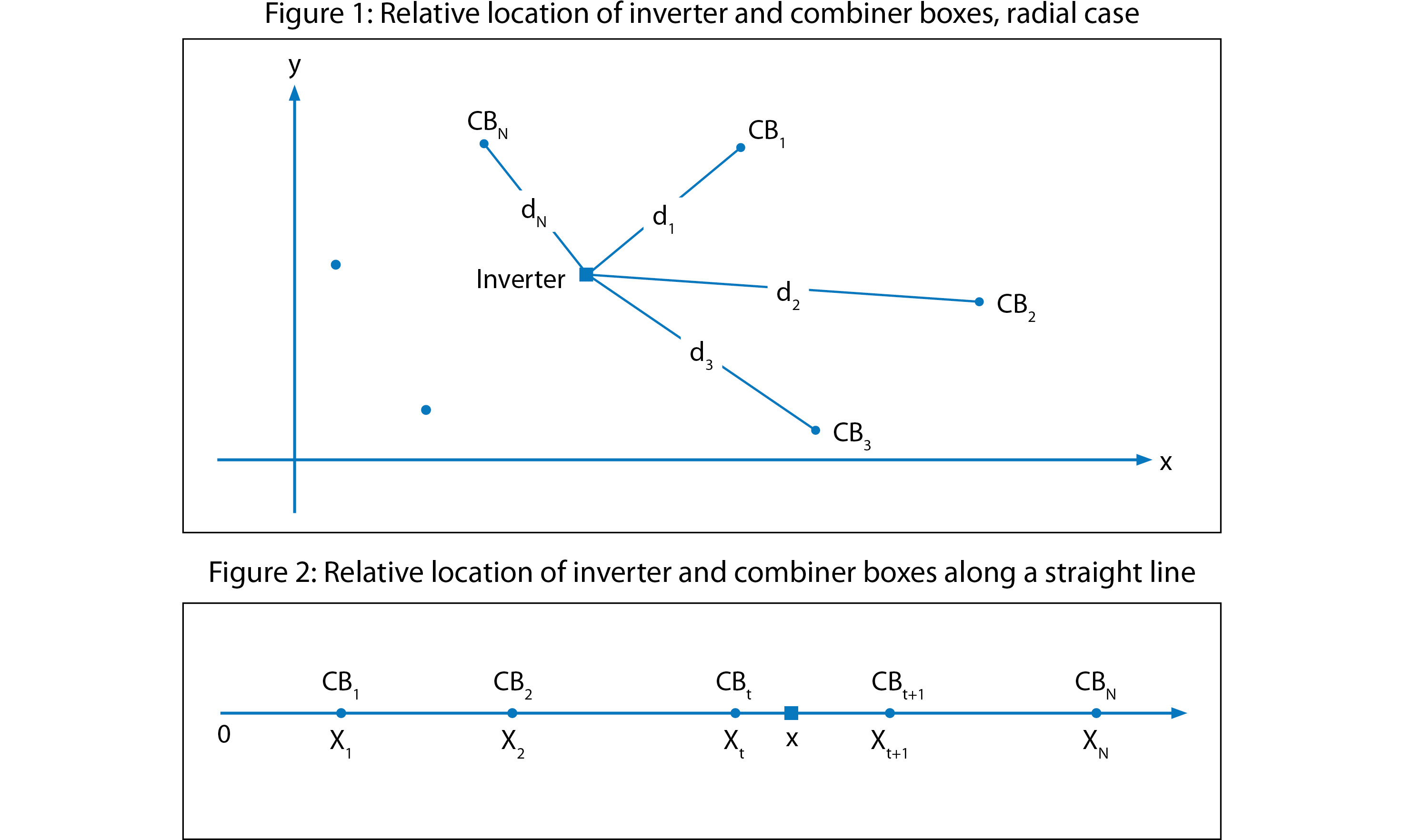
The configuration of the first case - where homeruns radially connect combiner boxes (CB) to the inverter along single straight lines - is represented in a general form in Figure 1.
Assume that N combiner boxes are located in the array field at coordinates (Xk , Yk) - with k being one of the combiner boxes numbered (k1 through kN). Each combiner box has a rated output current of Ik. Each of the homerun conductors from each combiner box to the inverter is given by the resistance per foot of each conductor as Rk for k1 through kN.
The total power loss (p) in the connecting conductors can be represented as equation (1), where pk is the power loss in the kth homerun, and dk is the distance of the kth combiner box from the inverter (x,y) given by equation (2).
Substituting for dk from (2) into (1) produces equation (3).
Differentiating power loss as a solved constant (P) once with respect to x and once with respect to y gives equations (4) and (5). Setting equations (4) and (5) equal to zero and solving for x and for y, we arrive at equations (6) and (7), respectively. Equations (6) and (7) give the coordinates of the inverter for the minimum total power loss (Pmin).
The pair of equations (6) and (7) cannot be solved explicitly for x and y because dk on the right-hand side of each equation depends on both x and y through equation (2). However, the pair of equations can be solved iteratively, and the solutions converge to the optimal point (x,y).
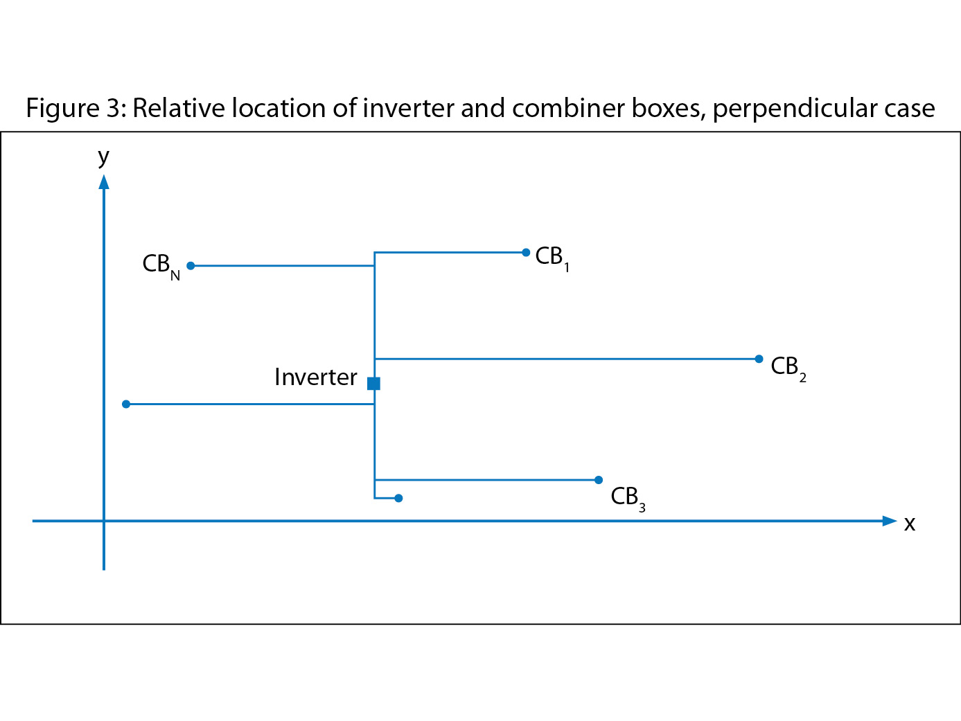

For an example of this approach in operation, Table 1 shows the x and y coordinates and rated currents of eight combiner boxes, along with the specific resistance of the conductors connecting them to the inverter.
Quantities given for x and y in the last two columns of the table show the result of the iterative solution of equations (6) and (7) corresponding to the optimal location of the inverter. The calculated distance for each combiner box to this inverter location and the power loss in each conductor are also shown.
For Table 1, the lengths are given in feet, current in amps, conductor sizes in circular mills (MCM), conductor resistances in ohms per foot and power in watts. Results for dk, pk, and x and y are rounded to the nearest whole number.
Perpendicularly connected homeruns
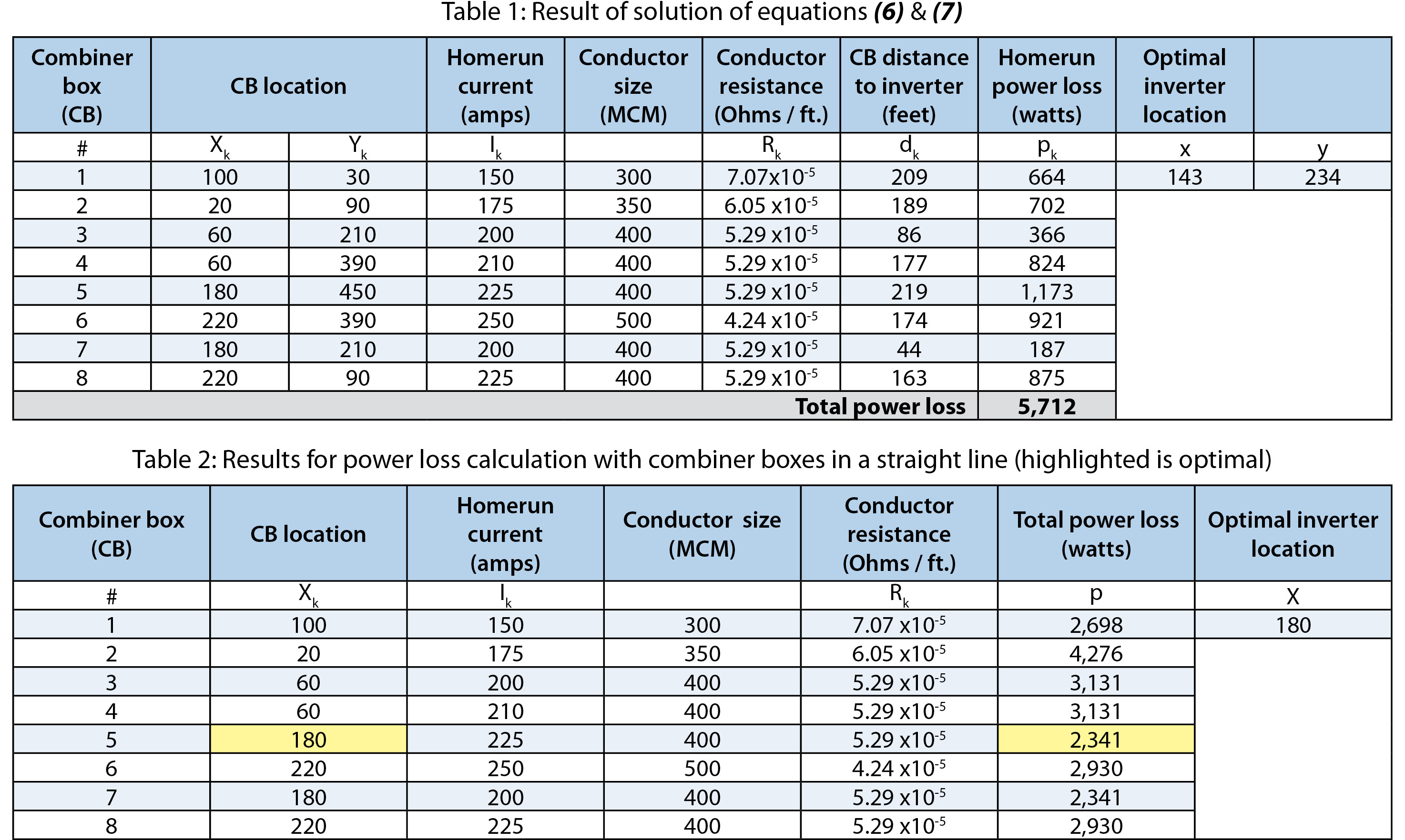
In the second case, homeruns are connected to the inverter along perpendicular line segments, which are typically in the direction of the racking and in the direction perpendicular to the racking.
To solve this configuration, start with a special situation in which N combiner boxes are located along a straight line with the x coordinate of each given. Pick a test point at coordinate x somewhere between two adjacent combiner boxes CBt and CBt+1 for tentative placement of the inverter, which is shown by the small square in Figure 2.
With pk, Ik, dk and Rk defined using the same procedure that the first case did, we have the total power loss, represented as p (8). Then, take the derivative of P with respect to x (9). The expression for the derivative of p with respect to x is independent of x.
We will now investigate circumstances under which this derivative passes through a critical point. It is seen that the derivative assumes a negative value when x is located to the left of CB1 and that it assumes a positive value when x is located to the right of CBN. Therefore, it must go through a change of sign as x is moved on the x-axis across the entire field of the combiner boxes.
However, because the value of the derivative is a constant while x is between each pair of combiner boxes, it must change sign exactly as x moves from one side of a particular combiner box to the other side of that combiner box. If the sign change is from negative to positive in going from the left-hand side of the box to its right-hand side, then p must have a local minimum at the location of that combiner box.
If the value of the derivative happens to be zero between a particular pair of adjacent combiner boxes, and a change of sign is encountered as we move off of the line segment, then the critical point can be taken to be any point on the line segment connecting the two adjacent boxes, including either of the two ends.
This argument shows that the optimal location of the inverter is in collocation with one of the combiner boxes.
Therefore, to find the optimal location for the inverter, it is sufficient to consider placement of the inverter with each of the combiner boxes and calculate the total loss for that location. The smallest calculated loss will determine the optimal location of the inverter.
For an example of this approach, Table 2 shows the results of calculation of total power loss, with the inverter in collocation with each of the eight combiner boxes located on a single straight line - some pairs of combiner boxes are located together in this example.
With the rated currents and resistances as given, the total power loss is calculated with the inverter collocated with each of the combiner boxes. As shown, the minimum power loss is attained when the inverter is collocated with CB5 - which is also the location of CB7. The corresponding location (x) for the inverter, therefore, is the coordinate of CB5 - which is 180 - for a total loss of 2,341 W.
As a general case, the layout of such a perpendicular arrangement is represented in Figure 3.
As before, the assumption is that the coordinates of the combiner boxes are given along with their rated current and conductor sizes. The coordinates of the inverter are taken to be (x, y).
The power loss is shown in equation (10), which is identical to (1). Each conductor path dk from a combiner box to the inverter consists of two straight line segments: one parallel to the x-axis and the other parallel to the y-axis. Designate these two segments as dxk and dyk, respectively.
For each combiner box k, we have dk = dxk + dyk. Substituting these into (10) results in equation (11).
Letting px represent the first sum and py the second sum in equation (11)results in equations (12x) and (12y). Now, p can be re-written as p = px + py.
Clearly, px is independent of dyk, and py is independent of dxk. This means we can temporarily set Yk = 0 for k1 through kN, thereby placing all of the combiner boxes on the x-axis. Then, we can find the x that minimizes px as was done in the special case earlier.
We repeat this procedure for the y-axis by setting the Xk = 0 for k1 through kN, finding the y that minimizes py.
The pair x and y that are found in this way do determine the optimal location of the inverter (x, y), and the total minimized value of p that corresponds to this placement of the inverter will be the sum of the minimized values of px and py.
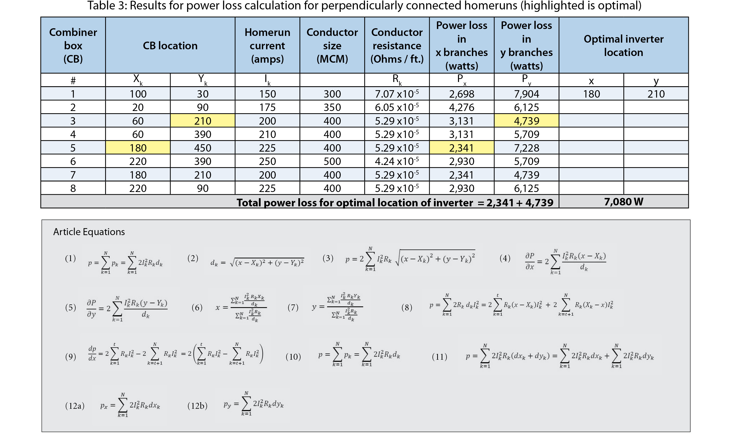
Given the same values for location, current and conductor sizes for eight combiner boxes as depicted in Table 1, the calculated losses in conductors in the x and in the y direction are shown in Table 3. The minimum of these losses are achieved with an inverter located at (180, 210), with a total minimized loss of 2,341 W + 4,739 W = 7,080 W.
In all of the above techniques, the actual resistance value varies along with temperature. If the conductors are all of the same material and all homeruns are subject to the same temperature change, then the constant will be the same for all conductors. If this is the case, then the optimized location will be so under all temperature conditions.
The current Ik of PV modules are taken to be proportional to the level of irradiance. As with temperature and resistance, the optimal location of the inverter is independent of the base irradiance for which Ik values were specified.
As a final note, the method outlined above can be applied to installations with string inverters connected to an AC panel. In such a case, the inverters play the role of the combiner boxes and the AC panel plays the role of the central inverter. The optimal location of the AC panel can be determined following an approach similar to the one presented above. S
Industry At Large: Optimizing Inverter Placement
Maximize Solar PV Power Generation By Optimizing Inverter Location
By Foad Alvandi
Designers can use the location of combiner boxes to place a central inverter and minimize loss.
si body si body i si body bi si body b
si depbio
- si bullets
si sh
si subhead
pullquote
si first graph
si sh no rule
si last graph