
301 Moved Permanently
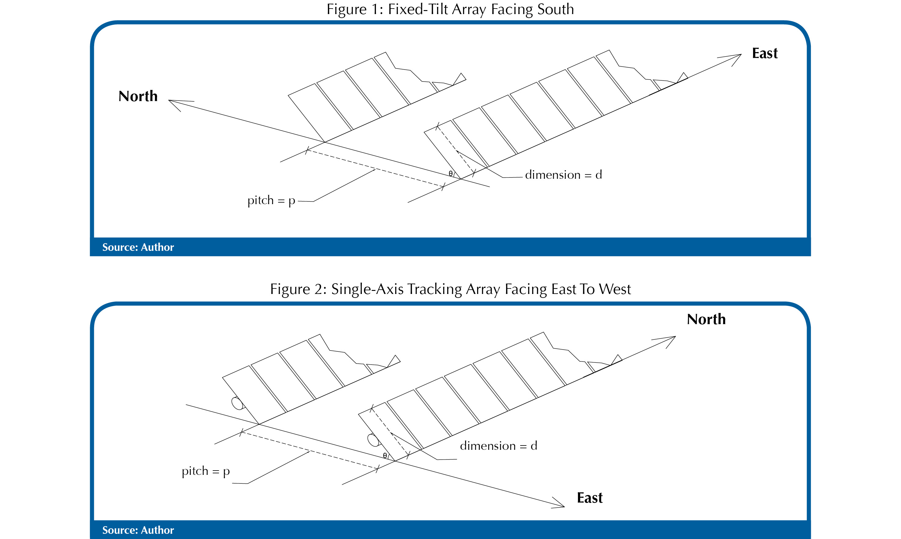
At the early stages of the design of a ground-mount photovoltaic system, the trade off between the pitch of the racking installation and the solar window at the winter solstice is one of the most important design considerations. For our purposes, “pitch” is defined as the distance between front edges of two successive rows (See Figure 1), while “solar window” is defined as the maximum number of hours during which no inner-row shading occurs.
Clearly, the greater the pitch for a given fixed-array tilt angle, the wider the solar window and, thus, the greater the kilowatt-hour (kWh) per kilowatt-peak (kWp) yield of the installation. However, this increase in productivity comes at the expense of smaller ground coverage ratio (GCR), which is defined as the total area of installed modules divided by the area of the footprint of the array on the ground. The smaller the GCR, the greater the land use and the longer the trench and conductor runs, given a fixed system size.
In cases when availability of land is limited, a smaller pitch allows increased kWp installation, albeit at a lower kWh/kWp yield due to the narrowing of the solar window. For the reasons just stated, as well as other economic and engineering considerations, it is important that the solar designers and financiers understand well the relationship between the two elements of pitch and solar window for the given project location and at the given module tilt angle.
For fixed-tilt installations facing directly south, calculating the pitch for a desired solar window - normally taken to be the window on the shortest day of the year - and for a given module tilt angle is relatively straightforward. What is needed is the sun’s position at the beginning or ending of the solar window for the location and the application of some trigonometry to relate the pitch and tilt with the solar window.
The altitude and azimuth of the sun - the sun’s position in the sky - for any location, date and time can be obtained from a website maintained by the U.S. Naval Observatory, at aa.usno.navy.mil/data/docs/AltAz.php.
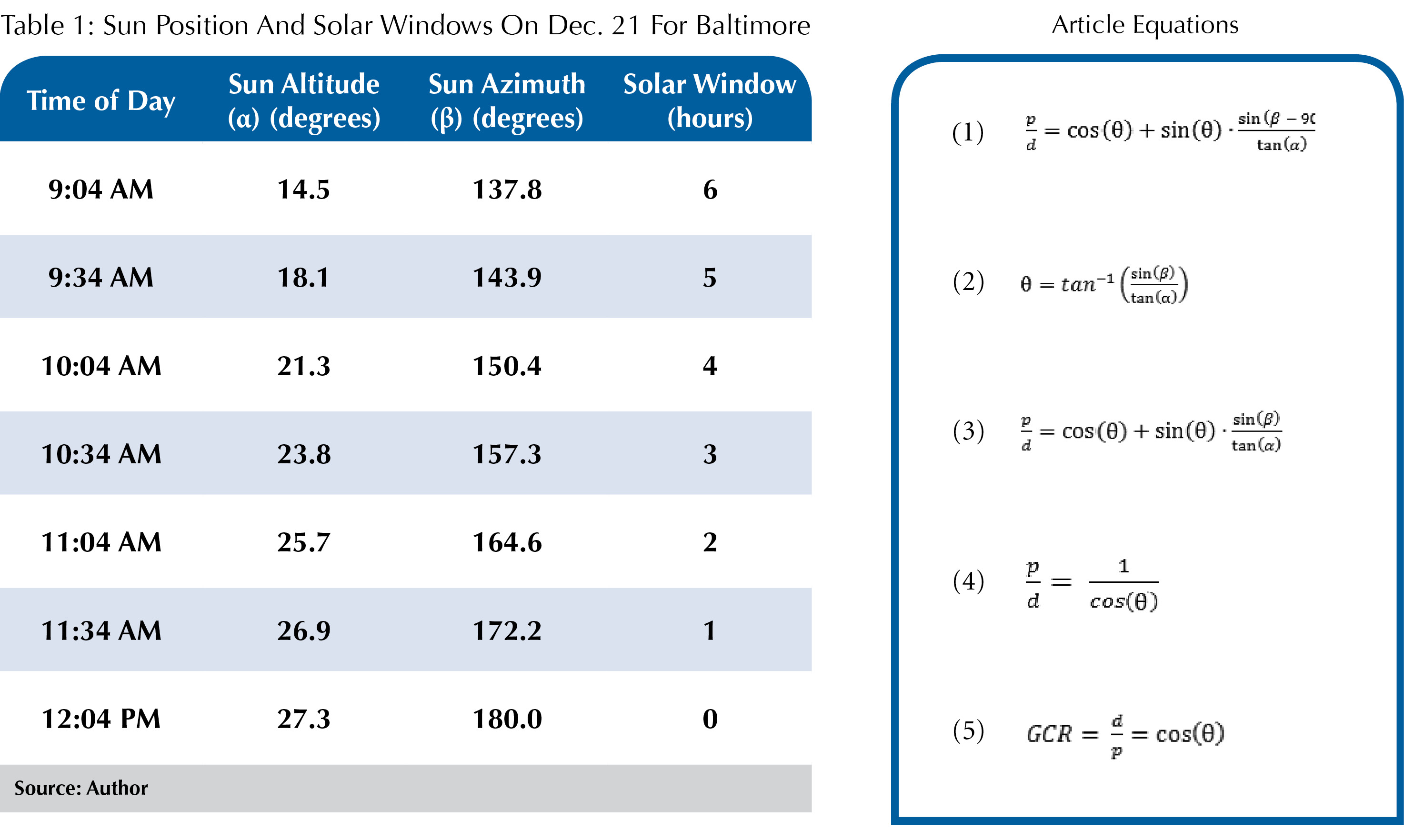
A sample download from this website for Baltimore (W 76° 37’, N 39° 19’) can be used to calculate a table of the sun’s position on Dec. 21 and the corresponding solar window. This is shown in Table 1. Starting at 9:04 a.m. (three hours before solar noon) in half-hour intervals through solar noon at 12:04 p.m. Observatory data is available - covering any desired time interval down to a resolution of one minute.

The remainder of this article examines the relationship between pitch and solar window for the case of 1) a fixed-tilt, south-facing installation and 2) a horizontal, single-axis tracker installation with a north-south axis of rotation.
Fixed-tilt configurations
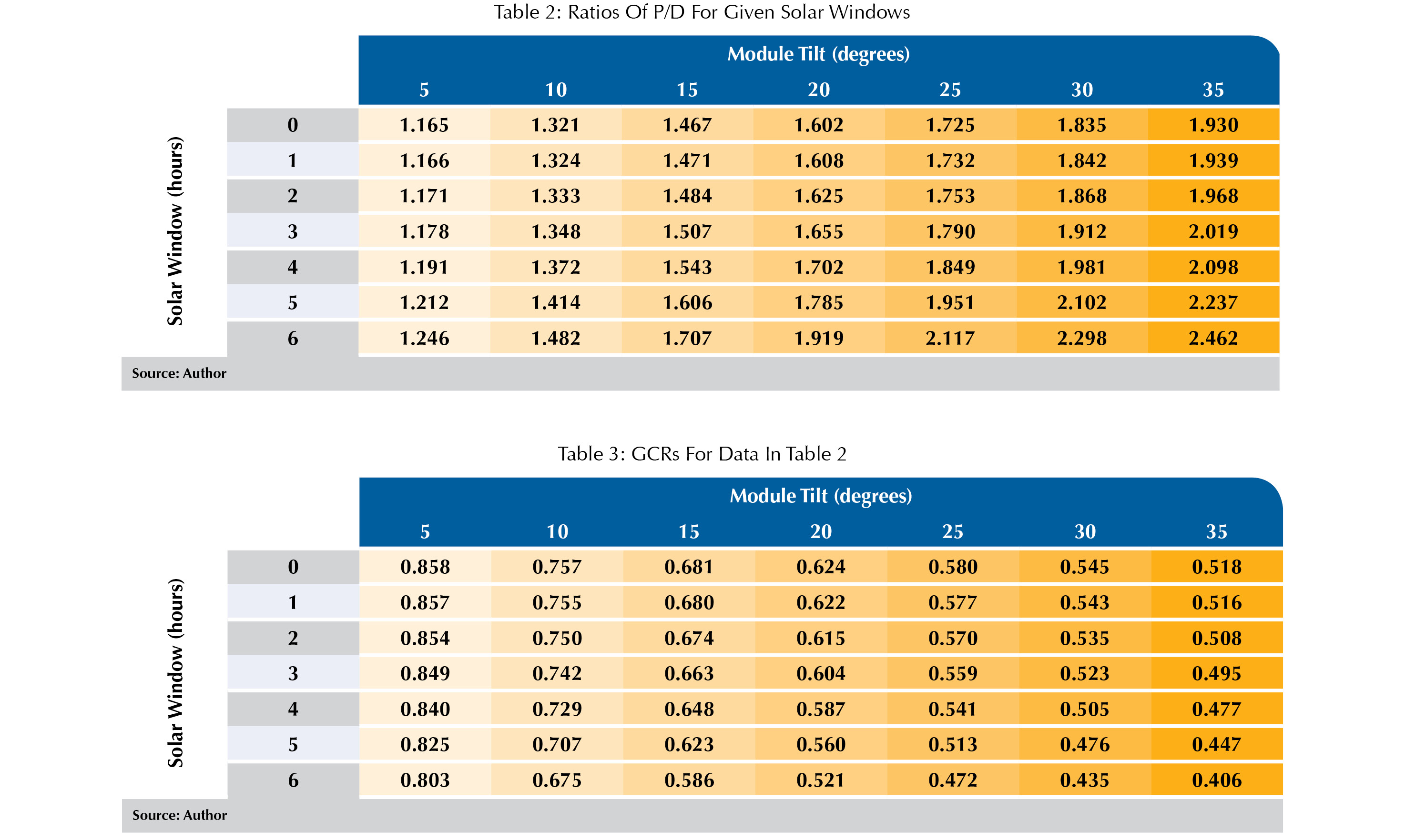
Figure 1 shows a portion of a fixed-tilt array of south-facing modules installed on a flat site at a tilt angle of θ with respect to the horizon. The pitch and dimension of the modules have been designated as p and d, respectively. Table 2 shows the ratio of p/d (height, in the direction of the tilt) calculated for south-facing arrays for locations near Baltimore over given solar windows on Dec. 21. Table 3 shows the corresponding GCR for each choice.

For example, to have a solar window of five hours on Dec. 21, given 77-inch by 39-inch modules installed at a 25° tilt in portrait configuration facing due south, the pitch is calculated as:
77 x p/d (1.951) = 150.23 inches (12.52 feet), with a GCR of 0.513 (51.3%).
Letting α and β represent the altitude and azimuth (east of north), respectively, of the sun at the start time of the solar window in the morning, letting θ represent the tilt angle of the module with respect to the horizon, and letting d represent the dimension of the module, the p/d ratios in Table 1 are calculated using Equation 1 (See Article Equations). Note that the position of the sun at the end time of the solar window in the afternoon could have also been used to calculate p/d; however, in that case, β in Equation 1 would need to be replaced with 360 - β.
Tracker configurations
Figure 2 shows a portion of a horizontal, single-axis tracker installation with a north-south axis of rotation at a moment in the morning, T hours before solar noon. Assume that the position of the sun at this moment is given by α and β for its altitude and azimuth, respectively, and the tilt angle of the arrays is θ° with respect to the horizon and facing due east. Angle θ is selected by the tracker’s controller so as to minimize the angle of incidence of the sun.

Due to the symmetrical apparent motion of the sun in the sky with respect to the north-south axis, it is clear that at time T hours after solar noon, the arrays will have the same tilt angle of θ with respect to the horizon, except they will be facing due west (not shown in the figure). Once again, this angle is automatically selected by the tracker controller.
For any location, α and β are known for any desired day and time; however, our efforts here involve a symmetrical window of time around solar noon on the shortest day of the year, normally taken to be Dec. 21.
Given the desired solar window on Dec. 21, we can first determine the position of the sun for the start time of the window on that day - for example, by downloading data from the U.S. Naval Observatory, as previously indicated - and calculate the optimal angle of tilt θ corresponding to the position of the sun at that moment. Knowing the three quantities of α, β and θ, we can then calculate the p/d ratio and the GCR.
For example, to have a solar window of five hours on Dec. 21, given 77-inch by 39-inch modules installed on north-south axes of a single-axis tracker with a longer dimension perpendicular to the axis, the pitch is calculated as:
77 x p/d (2.06) = 158.62 inches (13.22 feet), with a GCR of 0.485 (48.5%).
Such a tracker at this location will assume a tilt angle of 60.98° with respect to the horizon at the beginning and ending of the five-hour solar window.
This shows that if we install the rows with a pitch of 13.22 feet, there will be no inner-row shading. Because the tilt angles for the times within the solar window will be shallower than 60.98°, it is seen that no inner-row shading should occur for the duration of the solar window.
Given that solar noon occurs at 12:04 p.m. for this location on Dec. 21, the beginning and ending times for a five-hour window will be 9:34 a.m. and 2:34 p.m., respectively.
With α and β representing the sun’s altitude and azimuth as usual for a given time of day in the morning, the optimal angle of tilt θ is calculated as in Equation 2.
Once θ is known, p/d can be calculated in Equation 3.
However, combining equations 2 and 3, the expression for p/d can be simplified to Equation 4.
Subsequently, the GCR is calculated in Equation 5.
The techniques described in this article will enable designers of ground-mount arrays to figure out how to get the most productivity out of a site with a few straightforward calculations.
Optimizing Array Spacing
Find The Perfect Pitch For Ground-Mount Arrays
By Foad Alvandi
A few simple calculations can be used to determine optimal array spacing from any point in the world.
si body si body i si body bi si body b
si depbio
- si bullets
si sh
si subhead
pullquote
si first graph
si sh no rule
si last graph